ATOMIC A3 MANUAL
HANDLING INSTRUCTIONS – IMPORTANT
Only lift the unit from the metal frame upper.
Do not attempt to lift the unit by the plastic base cover.
The unit is heavy. Do not attempt to lift it alone.
Safety Precautions
- The A3 motion simulator (the system) is capable of moving the user very rapidly and sharply and is therefore potentially dangerous for use by those with conditions including but not limited to spinal / neck injuries / weaknesses, epilepsy, motion sickness, vibration injuries / susceptibility and any other condition which makes the user adversely affected by sudden movements & vibration. If someone is in any doubt over their fitness to safely use the system then they should not do so. If undecided, seeking medical advice may help someone to decide upon their fitness to use the system.
- The use of the system by children is entirely at the discretion of a responsible adult and we recommend that one be present at all times if children are using the system.
- The system is also capable of causing injury / damage to adults, children, animals and objects located too close to the system while in use. It is therefore imperative that a clear area is kept around the system while in use. Special care should be taken to ensure that children and animals are not able to enter this area.
- Ensure loose clothing is not in the proximity of any moving parts to reduce the risk of trapping or injury.
- In any event, all users of the system, and those who approve use of the system by others, do so at their own risk. All those in close proximity to the system whilst in use, including the user, bear responsibility for ensuring that they, children, animals and possessions are not placed in danger by being too close to the system whilst in use.
- The system is heavy (over 50Kg) and no attempt should be made by one person to lift the unit alone. When attempting to move the system, or parts thereof, safe lifting practices should be employed. Anyone attempting to move, or assist in moving, the system or parts thereof do so at their own risk. Any involvement by children in such movement is at the risk of a responsible adult.
- For maximum stability, the base should be mounted on a flat, level surface, with the front support legs extended and all support feet making good contact with the ground when a user is seated. The rear castors should be just above, or barely touching the ground.
- Neither Next Step Solutions Ltd nor their partners / affiliates shall accept any responsibility for injuries or damage to any person, animal or object, howsoever caused, in interaction with the system.
IMPORTANT: Please read this manual in full before attempting to assemble or use the Atomic A3. Failure to do so may result in damage, poor performance, reduced system life or injury.
Unpacking & Checklist
Most system components are factory pre-assembled. The table below shows the constituent components by System type.


- System
- A3 Motion Base
- Seat & seat fasteners
- Foot rest/pedal mount (2 parts)
- Steering wheel/flight yoke mount (2 parts)
- Shifter/throttle/shift panel mount & fasteners
- Flight stick / throttle side mount x 2
- USB Cable
- IEC Power Cable
- Motion Base
- Yes
- x
- x
- x
- x
- x
- Yes
- Yes
- Racing/Flight
- Yes
- Yes
- Yes
- Yes
- Yes
- x
- Yes
- Yes
- HOTAS
- Yes
- Yes
- x
- x
- x
- Yes
- Yes
- Yes
- Passenger
- Yes
- Yes
- x
- x
- x
- x
- Yes
- Yes
Tools Required
- 17mm spanner / adjustable spanner
- Small flat-head screw driver, 3.5mm wide tip ideal, < 4mm (TTi units only)
Additional Recommended Tools
- 13mm spanner
- 6mm allen key
- 5mm allen key
- Cable Ties or Velcro Straps (for securing controller cables)
MOTION BASE SETUP
Seat Installation & Adjustment
- Remove the Atomic A3 base unit from its packaging and situate it on a level, stable operating surface for intended use. WARNING: Never lift the base unit by the plastic housing, or damage may result to the mounts (the housing is ‘floating’ for safety reasons). Always lift from the front and rear of the metal top-table.
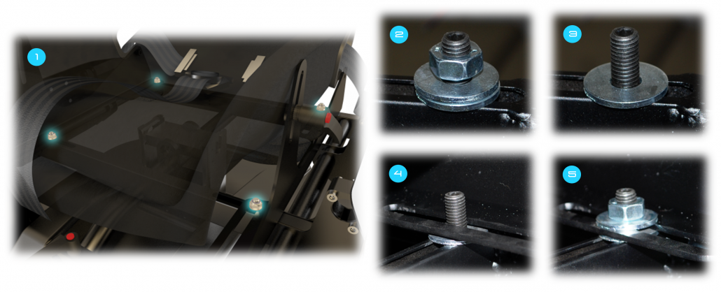
- Shows how each mounting post appears then the system is first unpacked, Remove the nut and top washer from all four mounting posts, leaving the lower washer in-place on each.
- OPTIONAL: The posts can be shifted laterally to support varying seat-widths if you are fitting your own seat. To do this, the mounting post can be loosened by inserting an allen key into the top of each post and turning anti-clockwise. Slide the posts to the position you require and re-tighten the posts by turning the allen key clockwise.
- Line up each of the seat rail slots with the mounting posts ensuring each rail is correctly seated on the bottom washer (4).
- Place the top washer onto each mounting post and screw down each of the four nuts on top of it (5). Do not fully tighten the nuts yet – tighten just enough so the seat can still slide forward and backwards along the rails. This is because the Centre of Gravity (COG) with need configuring once the system is fully assembled.
Tactile Transducers
(TTi-equipped systems only) – Connect the tactile transducers (attached to the bottom of the seat) to the two corresponding wires on the upper section of the base unit. Insert the bare ends of the wires into the terminal blocks and tighten the screw in each terminal (clockwise). Ensure that one wire is inserted into each terminal entrance and that red is connected to red and black to black on each side.

Support Legs
- Site the motion base on a level surface, and extend the support legs highlighted in the picture on the left. Ensure the plastic feet are making contact with the ground.
- For further stability, it is possible to mount the A3 base to a platform. If desired, please contact AMS for further information and advice.

Seat
Seat Adjustment
To adjust the seat reclination, loosen the levers shown in the figure by turning anticlockwise. Adjust the seat to the desired angle, then re-tighten the levers by turning clockwise. If surroundings hamper tightening, press and hold the red button on the lever (disengaging it from the tightening mechanism), turn anti-clockwise, release the button and further tighten clockwise.

Foot Rest / Pedal Mount installation & adjustment
Footplate (pedal mount plate)
- Attach the footplate to the stainless steel spine using the four thumbscrews (two each side) highlighted in the figure.
- The footplate may be installed at one of five different angles dependent on which of the front mounting holes in the footplate are used.
- This angle may be reset in the future by loosening the rear two screws and swapping the front mounting holes.

Footrest (pedal mount assembly)
- Locate the footrest mount slides on the base upper section highlighted in the figure and loosen the adjustment knob on the front slide.
- Insert the footrest spine into the slides as shown. If this proves difficult the knob may need further loosening. Ensure the spine is fully engaged in both slides.
- Reach adjustment of the footrest can be achieved by sliding the spine back and forth in the slides. Once the desired position has been attained tighten the knob to secure the footrest assembly.

Steering Wheel / Yoke Mount installation & adjustment
Control table
- Attach the control table to the crossbar assembly using the four thumbscrews (two each side) highlighted in the figure.
- The control table may be installed at one of seven different angles dependent on which of the front mounting holes in the table are used.
- This angle may be reset in the future by loosening the rear two screws and swapping the front mounting holes.
- Ensure all screws are fully tightened before use to avoid damage.

Control table & crossbar
- Locate the crossbar slides highlighted in the figure and loosen the two adjustment knobs on the slides.
- Insert the control table spine into the slides as shown. If this proves difficult the knobs may need further loosening. Ensure the spine is fully engaged in both slides.
- Height adjustment of the control table can be achieved by sliding the control table & crossbar assembly up and down the spine. Once the desired position has been attained tighten the knobs to secure the control table & crossbar assembly to the spine.

Steering wheel (flight yoke) mount
- Locate the steering wheel (flight yoke) mount slides on the base upper section highlighted in the figure and loosen the two adjustment knobs on the slides. They may be on the opposite side of the base to that in the figure, dependent on whether the unit is configured for left or right hand drive.
- Insert the control table spine into the slides as shown. If this proves difficult the knobs may need further loosening. Ensure the spine is fully engaged in both slides.
- Reach adjustment of the steering wheel (flight yoke) mount can be achieved by sliding the spine in and out of the slides. Once the desired position has been attained tighten the knobs to secure the steering wheel (flight yoke) mount.

Shifter / Throttle / Switch Panel Mount installation & adjustment
- Attach the shifter mount to the side plate of the crossbar as shown in the figure using the provided thumb screws. The height and reach of the shifter mount relative to the steering wheel / flight yoke mount will depend on the choice of mounting holes used.
- Ensure all screws are fully tightened before use to avoid damage.

Side Mounts installation & adjustment
- Attach the side mount to the base upper section as shown in the figure using the provided socket cap screws. A 5mm allen key will be required to tighten / loosen these screws. The height and reach of the side mount will depend on the choice of mounting holes used.
- Ensure all screws are fully tightened before use to avoid damage.

Installation of controls (optional)
The footrest, control table, shifter mount and side mount come pre-drilled to allow mounting of a number of commonly used control sets. Locate these holes and use screws & nuts (not provided) to attach your controls.
Control sets not accommodated as standard can be mounted by using straps or zip-ties but AMS recommend the user drill extra holes to allow positive mounting.
Other devices may also be mounted to these parts in a similar manner to provide for different applications.
Centre of Gravity (COG) Setup

In order to maximise the performance of your system, it is important the COG is configured correctly based on the controllers you wish to use (some pedal sets are significantly heavier than others for example). Prior to configuring the COG, ensure you have fully assembled the unit, attached your controllers and adjusted everything for comfort by following the previous instructions in this manual. NOTE: Significantly incorrect COG settings can be detrimental to performance and reduce actuator life!
- Ensure the power is ON (see the Operation section) and the actuators homed to their centre positions. With your back against the back of the seat (in normal seated position), press and hold the red stop button for > 5 seconds until the unit enters de-energised mode. If the upper motion platform does not fall to the front or rear (side to side movement is ok), the COG is balanced – proceed to step 4. If the COG is not balanced, proceed to step 2.
- If the motion platform falls to either the front or the rear, loosen the reach adjustment levers of the steering wheel and pedal mounts. Slide the seat forwards or backwards along its mounting rails (in the opposite direction to which the platform was falling), moving the wheel and pedal mounts by the same amount as the seat to maintain the driving position.
- Re-energise the actuators by pressing the black button (see the Operation section), and once homed repeat the above process from step 1 until the correct balance is achieved.
- When satisfied the COG is configured correctly, fully tighten the seat mounting nuts shown in the picture above, along with the wheel and pedal mount reach adjustment levers.
Note: In situations where many users will be riding (e.g. commercial settings), it is recommended the COG is configured for an average height user within the group to obtain the best results.
Wiring (Rear IO Panel)

- Mains power switch (illuminated when on)
- Fuse holder
- IEC (mains power) input
- Motion base DMX address
- ‘F’ (Function) button
- Indicator LEDS (top = controller status, bottom = power)
- DMX networking IO ports
- ‘R’ (Reset) button
- USB compatible port
- Audio input (TTi units only)
- Audio output (TTi units only)
Basic Setup
- Connect the supplied USB lead to the USB compatible port (9), and the other end to any available USB 1.1 (or above) port on your computer.
- Connect the supplied IEC Mains lead to the Mains inlet (3), and the other end to any available mains socket. The acceptable input voltage range is universally compatible with all standard mains power supply systems ( 100-240VAC, 50/60Hz).
Amplifier Wiring (TTi Units Only)
If you have a TTi enabled unit, the following additional (un-supplied) cables are required:-
- 1 x 3.5mm male > 3.5mm male jack cable.
- 1 x 3.5mm male > 2 x Phono (L/R) audio jack cable (optional).
- Connect one end of the 3.5mm male > 3.5mm lead to the ‘Speaker / Headphone Out’ port on your PC (please refer to your PC’s instruction manual if you require more information), and the other to the ‘Audio IN’ port (10).
- Connect your headphones / PC speakers / audio amplifier etc, to the ‘Audio OUT’ port (11).
- WARNING: Output levels of audio devices can vary and the amplifier supplied has a large adjustment range to ensure lower level signals can be amplified to a useful level (although too low a signal will still produce a weak tactile transducer response.) As a result it is possible to over amplify a strong input signal. Over-amplification will cause damage to the TTi system and will be noticeable by audible knocks and clicks from the transducers. If you hear these, turn the gain down until they disappear to avoid damage.
Operation
Power
- Once power is connected to the unit, ensure the AC power switch is on (1). The AC switch will illuminate.
User Interface Panel
The User Interface Panel is situated on the right hand side of the upper moving section of the simulator (see image below) and provides the user with basic control of the simulator. The user can start, stop and de-energise the device without having to have access to the computer driving it
- To start, press the small black button on the User Interface Panel (image right). The ‘Atomic’ logo should light up blue and the unit home to its centre-position, ready for operation. The unit is now in ‘Run’ mode.

- To stop motion at any time, push the large red button on the User Interface Panel. The light on the panel will illuminate red and the ‘Atomic’ logo light will go from blue to red.
- To de-energise the actuators, press and hold the red button for > 5 seconds
- To re-start motion, press the small black button.

Trap Detection Mechanism
- The trap detection mechanism will automatically stop the motion in the event that something becomes trapped between the upper and lower sections of the simulator, or hits the simulator’s base cover.
- The simulator will enter stop mode, motion will cease, the red LED situated between the start and stop buttons of the User Interface Panel will light up. The ‘Atomic’ logo will also turn red.
- To exit stop mode and resume normal operation, press the black button on the User Interface Panel.
Indicator LEDs
- When USB power (but notmains power) is connected, the power LED on the rear IO panel will be illuminated RED. When mains power (but not USB power) is connected, the power LED on the rear IO panel will be illuminated GREEN. When both power sources are connected, the power LED will be illuminated YELLOW.
- While powered, the status LED will flash slowly when no data is being received and flash fast when data is being received via USB.
DRIVER SOFTWARE INSTALLATION

The Atomic can be controlled using either a PC (via Actuate Motion software or similar), or DMX capable controller (refer to DMX Network Setup documentation).
A license to the Actuate Motion software is granted with your simulator. If you have not already received your license and download instructions, contact support@actuate-motion.com
https://actuate-motion.com/
Hints & Tips
- Adjust your system fully to find the perfect driving position before starting. The Atomic provides extensive adjustment to simulate many different types of vehicle layout, which can greatly enhance the feel of the system when configured properly.
- Ensure the COG is configured correctly as per section 9.
- Experiment extensively with your software settings to fine-tune your ride, in particular force level and pitch/roll movement range. As with any other system, incorrect settings may yield disappointing motion results, but a correctly tuned system can produce an incredible experience. Sometimes less is more – excessive force settings can result in ‘overshoot’ (producing a jittery feeling in flight-type applications), and excessive pitch/roll movement range settings can reduce the response of the system to more subtle feedback such as road surface detail.
- If you have a TTi unit, ensure your line level input (connected to the Audio IN port on the Atomic) has a strong signal and the volume output on your computer is set to maximum for the best results.
- If possible, secure your controllers firmly to their mounts using the mounting holes provided, as described in section 8.
- If you are using force-feedback controllers, use a high force setting – the Atomic gives a substantial amount of force-feedback, so if your usual controller force settings are low they may get a little lost in the experience.
- For additional immersion and a better perceived motion experience it is highly recommended either headphones or a loud audio system is used.
- For increased immersion still, use a large 3D ready screen, projector, multi-screen surround or Virtual Reality HMD setup. If possible, remember to switch off the lights!
Appendix C – Troubleshooting
| Problem | Possible Cause(s) | Possible Solution(s) |
|---|---|---|
| No motion, one or more actuators move freely | • Power disconnected. • Actuator overload triggered. | • Check power connected (main switch on and illuminated) and press the black button to enter run mode . • If unit in run mode, but there is still no motion, disconnect power and USB, then reconnect. |
| No motion, actuators locked in place | • Unit is in stop mode (LED on switch panel and ‘Atomic’ logo will be illuminated red). • Incorrect software settings. • Incorrect DMX channel setting | • Enter run mode by check that there is no load on the base plastic cover, such as something trapped between the upper and lower sections. • Ensure USB cable is correctly connected and system is present in Windows Device Manager (refer to Windows manual). • Check software settings to ensure system is enabled and force or pitch/roll movement range settings are not 0 (refer to software user manual). • Check game has been recognised in software and motion preview is showing movement. • Check DMX channel is set correctly and corresponds with that in software (refer to software user manual) |
| Poor motion output | • Incorrect software settings • Incorrect COG configuration | • Increase pitch / roll movement range and / or force setting in software (refer to software user manual). • Correctly configure the COG. |
| No or poor Tactile Transducer feedback (TTi units only) | • Audio cables not correctly connected. • PC sound output low or muted. | • Ensure audio cables are properly connected, PC sound output is set to full and audio cable is connected to correct port on soundcard. • Check TT Gain software settings (refer to software user manual). |
Click here to add your own text